Understanding various communication protocols like UART, SPI, CAN and I2C via ATMEGA328-P and NODEMCU (esp-8226)

Recently while working on a project utilizing Arduino and DHT11 sensor I faced a set of challenges which led me to dive deeper into the world of communication protocols, particularly SPI, I2C, and CAN bus modules.
Despite the initial simplicity of the project, I encountered roadblocks when attempting to expand its capabilities. Adding more sensors and modules ended up being trickier than I thought. It was then that I recognized the importance of comprehending and utilizing communication protocols to facilitate seamless interaction of various components.
Discovering Various Communication Protocols
Firstly what are Communication Protocols?
Communication Protocols are a system of rules and digital message formats enabling the transmission of information between devices. In other words they help in governing the two-way data communication between devices.
Why do we require Communication Protocols?
Communication protocols play a significant role in allowing different devices to communicate and transmit information to each other. In Embedded Systems, Communication Protocols are vital in the function of devices. Like wireless devices, embedded devices need to talk to each other in order to share useful data.
This communication typically follows a Master-Slave protocol architecture, where Masters (Microprocessors) command data transmission to and from Slaves (Sensors).
There are two types of Communication Protocols, namely intersystem or intrasystem protocols. Inter-system protocols, also known as external systems, facilitate communication between two devices. Intra-system protocols, also known as internal systems, facilitate communication within a single device.
Diving into SPI, UART, I2C and CAN-Bus Protocols
SPI - Serial Peripheral Interface
A serial peripheral interface (SPI) is an interface commonly used in computers and embedded systems to facilitate short-distance communication between a microcontroller and one or more peripheral integrated circuits (ICs). Multiple transmission lines or signal wires connect the SPI chips, enabling the microcontroller to exchange data with the peripherals. It is commonly used to send data between microcontrollers and small peripherals such as shift registers, sensors, and SD cards.
SPI is a synchronous, full duplex main-sub node-based interface. The data from the main or the sub node is synchronized on the rising or falling clock edge. Both main and sub node can transmit data at the same time.

4 wire SPI has 4 signals:
Clock (SPI CLK, SCLK)
Chip select (CS)
main out, sub node in (MOSI)
main in, sub node out (MISO)
MOSI and MISO are the data lines. MOSI transmits data from the main to the sub node and MISO transmits data from the sub node to the main.
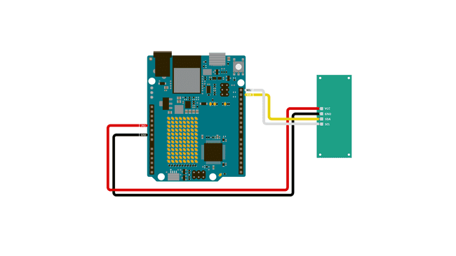
I2C.
The I2C protocol involves using two lines to send and receive data: a serial clock pin (SCL) that the Arduino Controller board pulses at a regular interval, and a serial data pin (SDA) over which data is sent between the two devices.
Each device in the I2C bus is functionally independent from the controller, but will respond with information when prompted by the controller.
I2C combines the best features of SPI and UARTs. With I2C, you can connect multiple slaves to a single master (like SPI) and you can have multiple masters controlling single, or multiple slaves.
Like SPI, I2C is synchronous, so the output of bits is synchronized to the sampling of bits by a clock signal shared between the master and the slave. The clock signal is always controlled by the master. I2C provides half duplex communication, so data transfer is not spontaneous between master and slave.
I mostly used I2C to reduce wire complexity connecting a LCD, replacing 16 wires to just 2 wires sending the same data.
UART
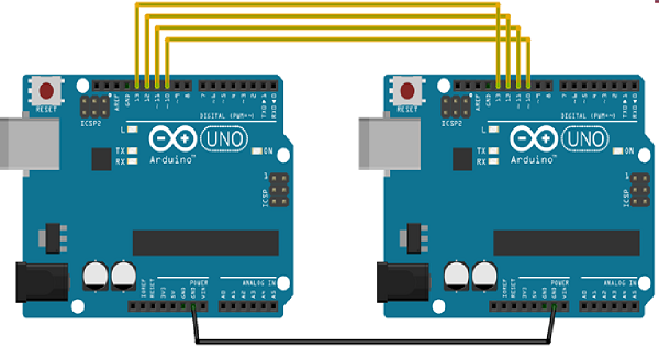
UART, or universal asynchronous receiver-transmitter, is one of the most used device-to-device communication protocols.

Two wires are established here in which only one wire is used for transmission whereas the second wire is used for reception. Data format and transmission speeds can be configured here. So, before starting with the communication define the data format and transmission speed. Data format and transmission speed for communication will be defined here and we do not have a clock over here that’s why it is referred to as asynchronous communication with UART protocol.
UART offers full duplex communication and is a bit different from traditional master -slave architecture.
UART helped me send data of local sensors (connected to Arduino) as API requests (sent from node-mcu) to read and write Realtime values.
CAN bus module
Fortunately I had this opportunity to collaborate with my friend Naman on his project on implementation of can bus where we built an intelligent auto control system with multiple nodes communicating via CAN bus and sending data to cloud.
In that project I explored working with MCP2551 CAN transceiver, transmitting the DHT11 Sensor data over a certain distance using the CAN protocol.

Controller Area Network also known as CAN-BUS is a common industrial bus because of its long travel distance, medium communication speed, and high reliability.
CAN bus uses two dedicated wires for communication. The wires are called CAN high and CAN low. The CAN controller is connected to all the components on the network via these two wires.
Typically the communication speed for CAN ranges from 50 Kbps to 1Mbps and the distance can range from 40 meters at 1Mbps to 1000 meters at 50kpbs. Standard communication protocols like UART, SPI, I2C are not much reliable in such fast paced systems.
Comparative Study of these protocols
| SPI | I2C | UART | CAN | |
| Speed | 3Mbps to 10Mbps | Standard: 100Kbps, Fast: 400 Kbps, Highspeed:3.4Mbps | 230–460 kbps | 10KBps to 1MBps |
| Type | Synchronous | Synchronous | Asynchronous | Asynchronous |
| No. of Wires | 4 Wires (MISO, MOSI, SCK, CS) | 2 Wires (SDA, SCL) | 2 Wires (RX, TX) | 2 Wires (Can_H, Can_L) |
| Duplex mode | Full Duplex | Half Duplex | Full Duplex | Half Duplex |
Sources
https://medium.com/@prathamesh.deore20/communication-protocols-in-embedded-systems-f7f467ebfa7b
https://how2electronics.com/interfacing-mcp2515-can-bus-module-with-arduino/